A still car, moving air and a chopped-off tail: how aerodynamic testing works, why simulation has not retired the tunnel, and where the Kammback fits.
Cars are held still in a wind tunnel while air is driven past them, and the forces on them are measured. Computational fluid dynamics simulates the same flow in software but still needs tunnel data for validation. The Kammback tail, developed in the 1930s, cuts drag with an abrupt rear end.
A car that is sitting perfectly still can be tested as though it were hurtling down a road, because the air does the moving. That is the trick behind the wind tunnel, an idea that grew out of whirling arms and is still used to check the computer simulations that were meant to replace it. Alongside it sits computational fluid dynamics (CFD), and an odd, chopped-off tail called the Kammback that taught designers a car does not need a long taper to cheat the wind.
How are cars aerodynamically tested in a wind tunnel?
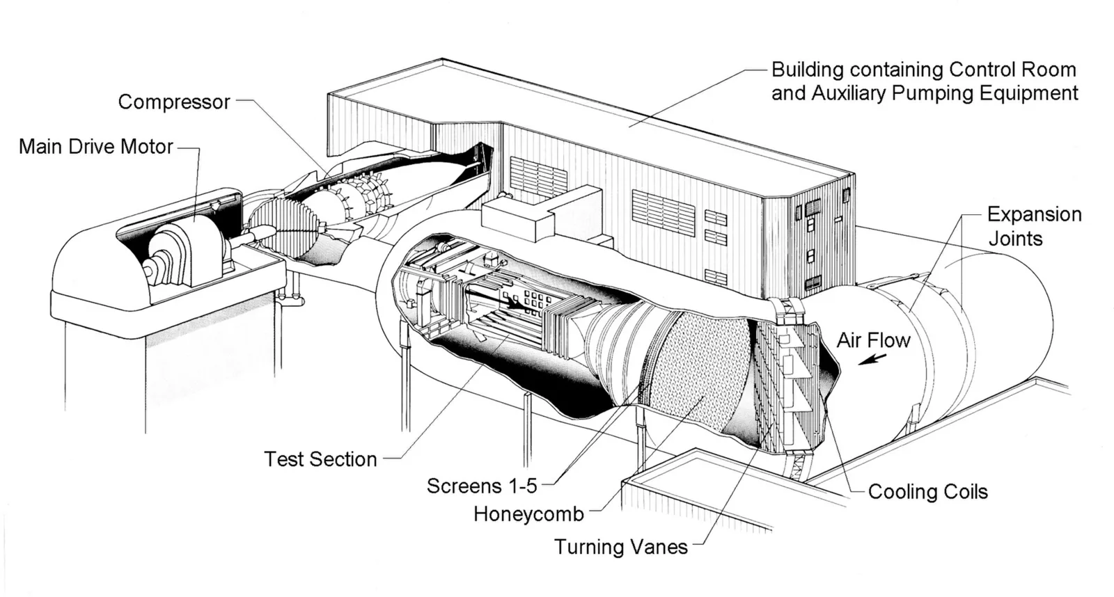
A wind tunnel is a device that produces a controlled stream of air for aerodynamic experiments. The experiment happens in the test section, with ducting to carry air in and out and a fan to keep it moving. Engineers use tunnels to see how air acts on an aircraft in flight or a road vehicle in motion, and to gauge what wind does to buildings and bridges. Test sections range from less than a foot across to more than 30 m (100 feet), and air speeds run from a light breeze to hypersonic.
The key move is to reverse the usual situation. Rather than a still atmosphere and a moving machine, the machine is held still and the air is driven past it. That brings the open air indoors under full control, so forces can be read off an object that is not moving at all. It is far cheaper and more convenient than measuring a vehicle that is actually travelling. The object, often a scale model, is restrained in the test section while air flows around it and instruments record the forces. Results from the reduced-scale model apply to the full-size machine, and the work is done rapidly and economically compared with testing the real thing.
Why a model behaves like the real car
The scientific justification came from the English physicist Osborne Reynolds of the University of Manchester. He showed that air will move over a scale model in the same pattern as over the full-size vehicle, provided one flow parameter is identical for both. That parameter, the Reynolds number, governs how flow patterns take shape, how well heat transfers and when turbulence begins. It is the reason engineers can trust a smaller object in a tunnel to speak for a larger one on the road.
The climatic wind tunnel
Not every tunnel is about drag. A climatic wind tunnel puts a car through extreme conditions to confirm that the air conditioning can keep the cabin comfortable when it is scorching or freezing, and that windows stay free of condensation in damp, cool weather.
Taking the sloping tail to an extreme produced an airfoil effect that lifted the rear of the car at speed.
From whirling arms to Eiffel's tunnel
Before tunnels there were whirling arms. Benjamin Robins built one to measure drag, and Sir George Cayley used another, 1.5 m (5 feet) long, that reached speeds of 3 to 6 m/s (10 to 20 feet per second) to compare the drag and lift of different airfoils. Whirling arms give an unreliable flow, though. Centrifugal forces intrude, and the object is always moving through its own wake, which makes detailed study of the airflow difficult.
Francis Herbert Wenham tackled both problems in 1871 by designing and running the first enclosed tunnel. Technical data then came quickly, and Wenham and John Browning, a colleague, are credited with finds including the measurement of lift-to-drag ratios and the benefit of a high aspect ratio.
In 1909 Gustave Eiffel built his first open-return tunnel in France, driven by a 50 kW (67 hp) electric motor, close to the base of his famous tower. Between 1909 and 1912 he ran about 4,000 tests. When his laboratory moved to Auteuil in 1912, his tunnel with a 2 m (7 foot) test section went with it, and it is still operational. Eiffel improved the design by boxing the test section inside a chamber, giving it a flared inlet with a honeycomb to straighten the flow, and placing a diffuser between that section and the fan. The open-return low-speed tunnel is often called the Eiffel type.
Scale grew fast. The US Navy built one of the world's biggest tunnels in 1916. In 1931 the NACA completed a tunnel at Langley measuring 9.1 by 18.3 m (30 by 60 feet), powered by two fans driven by 3,000 kW (4,000 hp) motors and able to take full-size aircraft. In 1941 a tunnel at Wright Field, Ohio, ran two 12 m (40 foot) fans from a 30,000 kW (40,000 hp) motor to test large models at 640 km/h (400 mph). Most of that growth was driven by aircraft, though the same principle serves cars.
CFD in car design: the wind tunnel in software
Computational fluid dynamics uses numerical analysis and computers to solve problems that involve flows. Software simulates the free flow of a fluid and its interaction with surfaces defined by boundary conditions, and supercomputers can give better answers for the largest, most complex problems. It is applied to a wide range of fields, including aerodynamics, weather simulation, engine and combustion analysis, and the visual effects behind films and games.
The basis of almost every CFD problem is the set of Navier-Stokes equations, which describe how single-phase fluids flow. Drop the terms for viscous action and you get the Euler equations. Remove the terms for vorticity as well and you reach the full potential equations, and linearise those for small disturbances and you have the simplest set of all. Over the decades CFD has worked its way from the simplest set towards the full Navier-Stokes equations as computers became powerful enough to handle more of the physics.
How CFD grew up
One of the earliest calculations resembling modern CFD was by Lewis Fry Richardson. It divided physical space into cells and used finite differences. It failed badly, but it and his 1922 book laid the groundwork for modern CFD and numerical weather forecasting, and early calculations on the ENIAC computer in the 1940s used methods close to his.
The first computer modelling of flow governed by the Navier-Stokes equations was probably done at Los Alamos National Laboratory, by a group under Francis Harlow, who is widely seen as a pioneer of the field. From 1957 to the late 1960s it developed a variety of methods for transient two-dimensional flows. The first three-dimensional paper appeared in 1967, from Douglas Aircraft's John Hess and A.M.O. Smith. It covered the surface of the geometry with panels, which gave this family of programs the name panel methods, and it was applied mainly to ship hulls and aircraft fuselages. VSAERO, the most widely used program of the class, has been used in the development of submarines, ships, automobiles, helicopters, aircraft and wind turbines.
Panel methods could not handle the non-linear flow of transonic speeds, so developers moved to full potential codes, then Euler equation codes, and finally the Navier-Stokes equations that were the ultimate target. NASA contributed codes such as ARC3D, OVERFLOW and CFL3D, and the work led to numerous commercial packages.
Why wind tunnels are still used
| Method | How it works | Strength | Limit |
|---|---|---|---|
| Whirling arm | Object swung round on an arm | Early drag and lift measurements | Unreliable flow; object moves in its own wake |
| Wind tunnel | Object held still, air driven past it | Cheaper and more convenient than moving tests; scale models can stand in for the full-size vehicle | Facilities are costly to run and many have closed |
| Climatic tunnel | Cars exposed to extreme heat, cold and humidity | Checks air conditioning and window clearing | Not designed for drag measurement |
| CFD | Numerical simulation of flow around surfaces | Reduces demand for tunnel time | Cannot yet model every real-world problem accurately |
Better CFD has lowered the demand for tunnel time without ending it. Plenty of real-world problems still defeat simulation, and trust in any numerical tool rests on checking its output against experimental measurements, which tunnels can supply. Validation of new software typically starts with a wind tunnel, then draws on earlier analysis, and ends with full-scale testing.
That has consequences for the facilities. Many American tunnels were decommissioned between 1990 and 2010, including historic ones, under pressure from declining or erratic use, high electricity costs and the value of the land. Yet validation of CFD still needs tunnel data, and this is likely to remain true for the foreseeable future. Research drones have taken over some traditional tunnel work, and the fastest wind tunnel in the world as of 2019 is LENS-X in Buffalo, New York.
What is a Kammback?
A Kammback, also called a Kamm tail or K-tail, is a rear-end shape in which the car slopes downward and is then cut off abruptly by a vertical or near-vertical surface. It reduces aerodynamic drag, which improves efficiency and cuts fuel consumption, while keeping a body that is practical to build and use. It is named for the German aerodynamicist Wunibald Kamm, who developed the design in the 1930s.
Where the Kammback came from
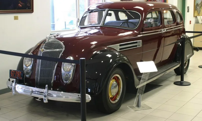
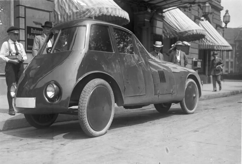
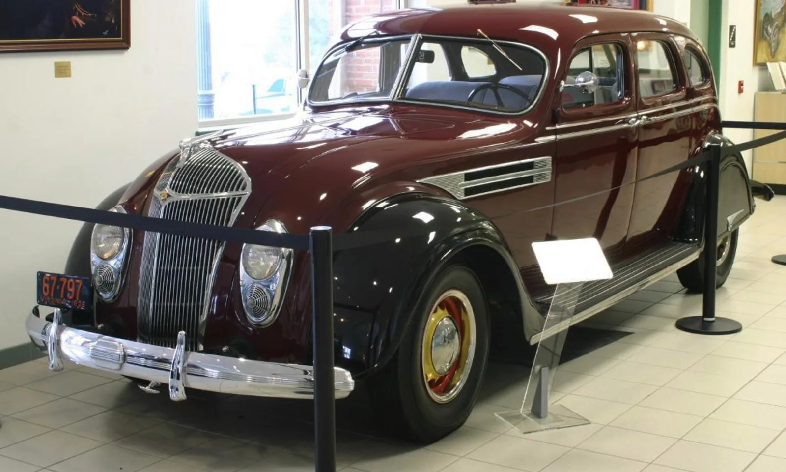
As car speeds rose in the 1920s and 1930s, designers began to apply aerodynamic principles. Drag demands energy, and therefore fuel. In 1922 Paul Jaray patented a car with a teardrop profile, a rounded nose and a long tapered tail, and the streamliners of the mid-1930s, including the Tatra 77, Chrysler Airflow and Lincoln-Zephyr, followed his discoveries. But a long tail makes a poor shape for a practical car.
In 1935 the German aircraft designer Georg Hans Madelung showed ways to cut drag without one. In 1936 Baron Reinhard Koenig-Fachsenfeld devised a smooth roofline that stopped at an abrupt vertical face yet gave drag as low as a streamlined body; he was working on a bus design and patented the idea. He then worked with Kamm at Stuttgart University, looking for shapes that gave a good compromise between everyday utility and an attractive drag coefficient. Kamm also emphasised stability, and proved the design's effectiveness mathematically and by experiment.
In 1938 Kamm built a prototype from a BMW 328. With other aerodynamic changes, the Kammback shape gave it a drag coefficient of 0.25. The first mass-produced cars built on these principles were America's Nash Airflyte (1949 to 1951) and Europe's Borgward Hansa 2400 (1952 to 1955).
Why cutting the tail off works
The ideal low-drag shape is a teardrop, but road vehicles cannot be that long. Kamm and other researchers found that chopping the tail off abruptly added little drag. The reason is the turbulent wake that forms behind the vertical surface. It behaves like the tapered tail it replaces: free-stream air does not enter it, so the airflow stays attached and smooth and drag is kept low.
Kamm's design truncates the tail where the cross-section is 50 per cent of the car's maximum. He found that to be a good compromise, since by that point the turbulence usually seen on flat-backed vehicles has largely gone at typical speeds.
The shape also helped with lift. As sports car racing speeds climbed during the 1950s, aerodynamic lift grew serious. Taking the sloping tail to an extreme, as on the Cunningham C-5R, produced an airfoil effect that lifted the rear at speed, risking instability or loss of control. The Kammback reduced the area of the lifting surface and created a low-pressure zone beneath the tail. By 1959 racing cars with full bodywork were using it to resist lift, and within a few years virtually all of them had it. Studies of the shape suggest that adding a rear spoiler is not beneficial at the angles tested, because overall drag increased.
Cars with a Kammback
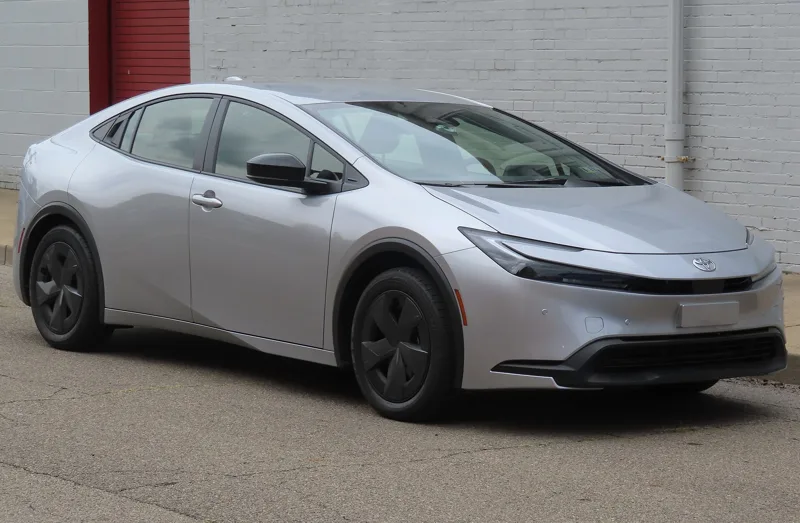
The list is long and varied. True Kammbacks include the 1958 to 1963 Lotus Elite, the 1962 to 1964 Ferrari 250 GTO, the 1965 to 1968 Ford GT40, the 1970 to 1978 Datsun 240Z, the 1974 to 1991 Citroen CX, the 1983 to 1991 Honda CR-X and the 1999 to 2005 Audi A2. The design returned in the early 2000s as a way to cut fuel use in hybrids, with the Honda Insight of 2000 to 2006 and the Toyota Prius, in production from 2004. More recent examples include the Hyundai Ioniq (2017 to 2022), the Tesla Model Y (from 2020) and the Aston Martin Valour (from 2024).
Be careful with labels. The Chevrolet Vega Kammback wagon of 1971 to 1977 and the AMC Eagle Kammback of 1981 to 1982 carried the name without following the aerodynamic philosophy, as did the AMC AMX-GT and the Type K concepts built on the Pontiac Firebird. Coupe-style SUVs such as the BMW X6 and Mercedes-Benz GLC Coupe are described as using a sort of Kammback shape, with more lumps and bumps than a proper one.
Where this goes next
The tunnels and the software are not on course to replace one another. CFD will keep needing tunnel data to prove its results, and in the United States, studies of future military and commercial tunnel needs have been done and others are under way, though their outcome remains uncertain. On the Kammback side, the shape is still in production in hybrids and electric cars.
What it means for a buyer or a driver
When a car is sold on a low drag figure, the number was probably produced by a combination of tunnel time and simulation, not by either alone. And the sloping-then-chopped tail on a hatchback or hybrid is usually not decoration. Where it follows Kamm's idea, it is doing the work of a long taper in far less length, which is why the same basic shape has carried race cars, family hatchbacks and hybrids across many decades.