A fluid coupling with a stator that turns a sluggish engine into usable pulling power, from the 1949 Packard Ultramatic to forklifts, buses and diesel locomotives.
A torque converter is a fluid coupling between engine and gearbox in an automatic car. Its stator redirects oil so that output torque rises above input at low speed, and a lock-up clutch later links the parts directly for efficient cruising.
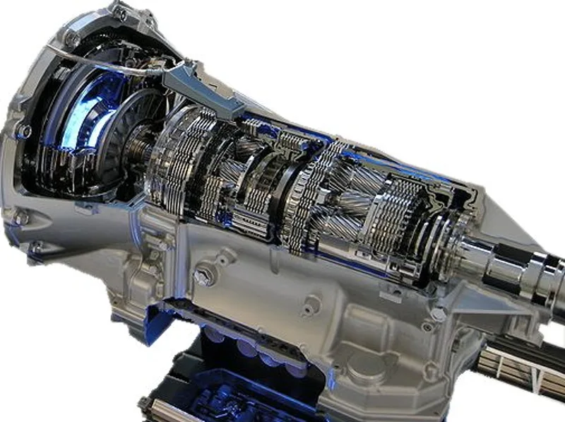
A torque converter is a device, usually a type of fluid coupling, that transfers rotating power from an engine to the gear train of an automatic transmission. It sits between the engine's flexplate and the transmission, and it is the automatic's equivalent of a clutch. Unlike a plain fluid coupling, it multiplies torque when the output turns slowly, which lets a car pull away from rest without a clutch pedal.
What is a torque converter?
A torque converter connects the prime mover, such as an internal combustion engine, to the automatic gear train, which then drives the load. In a manual car the mechanical clutch does a similar job, but the converter also increases the torque passed along when the output shaft is turning more slowly than the input. A simple fluid coupling can match speeds, yet it cannot multiply torque, so the converter adds a stator to provide that extra effort.
Most automatic transmissions in cars, buses and on-road and off-road trucks use the hydrodynamic type. Many also include a lock-up function to connect input and output directly when conditions allow, which avoids the losses of moving torque through fluid. Hydrostatic converters are used in small machines such as compact excavators.
A fluid coupling with a stator that recovers energy from returning oil, turning a slow turbine into torque for pulling away.
How does a torque converter multiply torque?
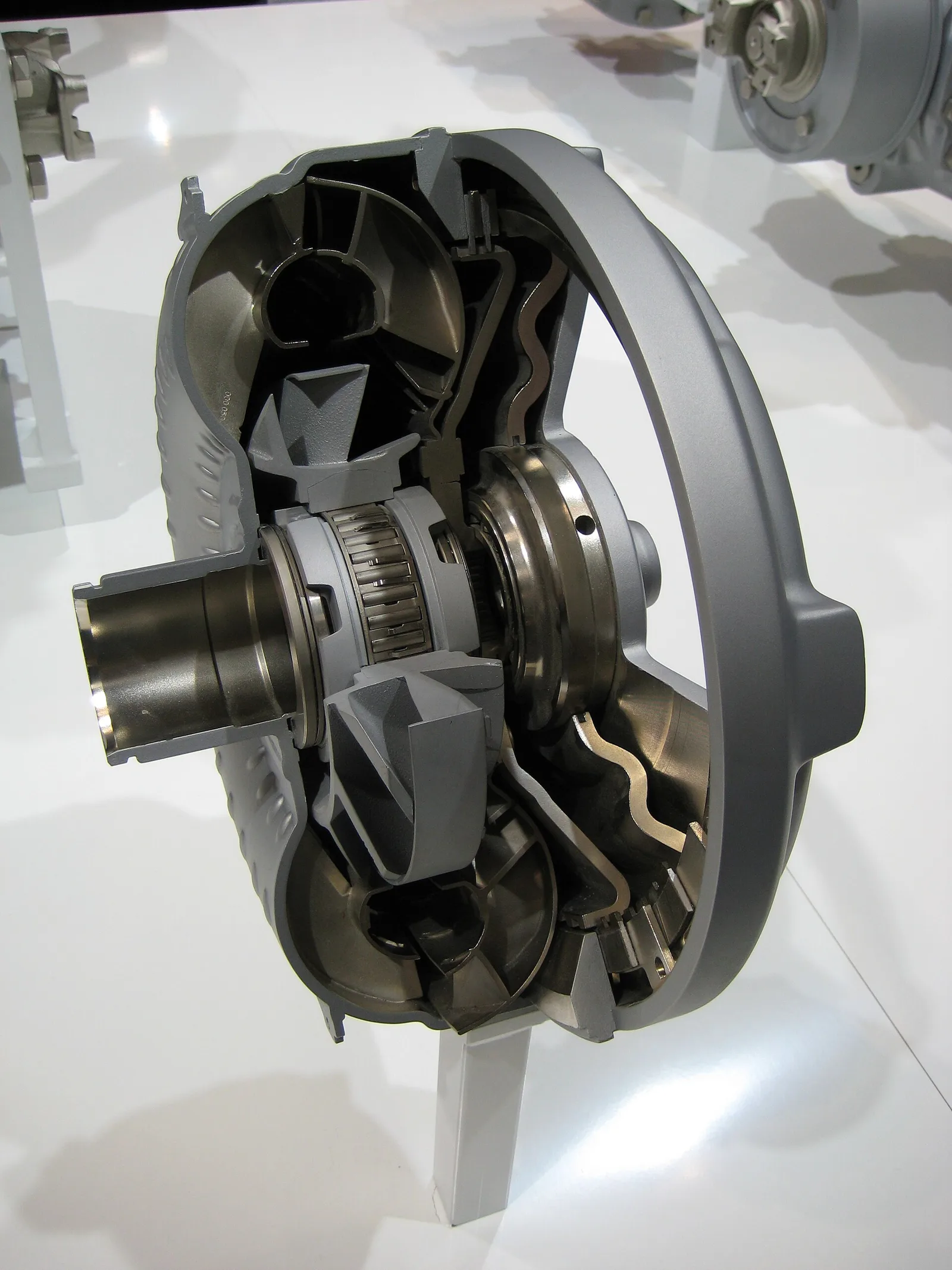
A torque converter has at least three rotating elements. The impeller is driven by the engine and throws oil outward. The turbine is connected to the output and is pushed by that oil. The stator sits between the impeller and turbine, so it can redirect the oil returning from the turbine before it reaches the impeller again.
In the classic design the stator never turns, which gives it its name. In practice it sits on an overrunning clutch that stops it counter-rotating against the engine while letting it turn forward. During slippage, returning oil would normally oppose the impeller, but the curved stator blades redirect it to help the impeller spin, and the energy of that returning fluid is recovered and added to the input. The result is more fluid moving to the turbine and a higher output torque.
The blades are angled and curved rather than straight, as on a plain fluid coupling. Small changes to blade shape can noticeably change performance, which is why converters are designed carefully for the engine and vehicle they serve.
What happens during stall, acceleration and coupling?
A torque converter moves through three operating phases. The table summarises them, along with the lock-up stage that most cars reach at cruising speed.
| Phase | What happens | Torque multiplication |
|---|---|---|
| Stall | Engine applies power but the turbine cannot turn, for example with the brakes held | Maximum, known as the stall ratio |
| Acceleration | The load moves and the speed difference between impeller and turbine is still large | Less than at stall, falling as the speeds converge |
| Coupling | The turbine reaches about 90 percent of impeller speed | Essentially ceased, acting like a fluid coupling |
| Lock-up | A clutch links turbine and impeller directly | None; the drive is purely mechanical |
In the stall phase the turbine is held still while the engine turns the impeller, so the converter gives its greatest multiplication. That phase also occurs briefly when a load first starts to move, because the speed difference is very large. Acceleration follows, with multiplication tapering as the turbine catches up.
Coupling begins when the turbine approaches the impeller's speed. Returning oil now turns the stator forward, the stator clutch releases, and the parts turn more or less as one unit. Modern automatics usually apply the lock-up clutch at this stage to improve fuel economy.
How efficient is a torque converter?
A torque converter cannot reach 100 percent efficiency. A classic three-element converter has an efficiency curve shaped like an arch, starting at zero at stall, rising during acceleration and falling in the coupling phase. The dip in coupling comes from the turbulence the stator creates, which is why the one-way clutch was introduced.
Maximum multiplication depends on the size and shape of the turbine and stator blades. Typical stall ratios for automotive applications range from 1.8:1 to 2.5:1, while specialised converters for industrial, rail or heavy marine systems can reach 5.0:1. High stall-ratio converters tend to be inefficient near coupling speed, whereas low-ratio converters give less multiplication. Drag racing transmissions use high stall speeds for quick starts, and highway vehicles use lower ratios to limit heat and feel firmer.
Losses in the converter produce waste heat, a problem most noticeable at stall. Blade geometry in modern designs keeps oil velocity low at low impeller speeds, which allows the turbine to be held stalled for long periods without serious overheating, as when a car in gear waits at a signal.
Why did lock-up clutches come and go?
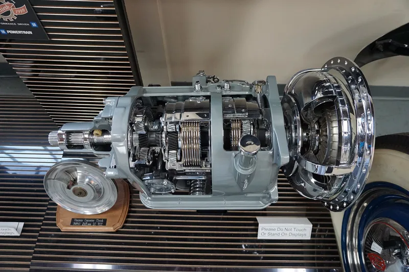
The lock-up principle appeared first in Packard's Ultramatic transmission, introduced in 1949. It locked the converter at cruising speed and released when the throttle was floored or the car slowed. Some Borg-Warner transmissions of the 1950s used the same idea, but it fell out of favour because of its added complexity and cost.
Lock-up clutches came back in the late 1970s as demand for better fuel economy grew. They are now nearly universal in automotive applications, where they eliminate slippage and almost all of the power loss during cruising.
Which converter variants were built?
Several designs added more elements to widen the range of multiplication. The Buick Dynaflow was a non-shifting automatic that relied on the converter alone for most of its multiplication, and it used a five-element converter to move a heavy car. Its later Triple Turbine Dynaflow and Chevrolet's Turboglide also used multiple turbines or stators.
Some General Motors transmissions used a variable-pitch stator, whose blade angle changed with engine speed and load. At the normal angle it gave moderate multiplication with better efficiency. When the driver opened the throttle abruptly, a valve moved the stator to a steeper angle for more multiplication at the expense of efficiency. Multiple-element converters are more common in industrial equipment than in cars.
What causes torque converter failures?
Overloading a converter can cause several failure modes, some of them dangerous:
- Overheating from continuous high slippage, which can damage the elastomer seals and thin the fluid. Rocking a stuck car back and forth between drive and reverse is a typical cause.
- Stator clutch seizure, where the one-way clutch locks solid, usually after severe loading and galling. Fuel consumption rises sharply and continued running usually overheats the unit.
- Stator clutch breakage, often from a neutral start in which engine speed is raised before a gear is engaged. The stator then counter-rotates and almost no power is transmitted.
- Blade deformation or fragmentation after abrupt loading or overheating, which can cause severe efficiency loss and, in extreme cases, catastrophic destruction.
- Ballooning, where prolonged or abrupt loading and very high speeds distort the housing. In extreme cases the housing can rupture and throw hot oil and metal over a wide area.
Strengthening helps. High-performance, racing and heavy-duty converters are often furnace brazed, a process in which molten brass fills seams and joints to bond blades, hubs and rings more firmly. The brazing also produces a small radius where each blade meets its hub, which reduces turbulence and improves efficiency.
Where are torque converters used?
Automatic transmissions in cars, buses and trucks are the most familiar use. Torque converters also drive diesel-hydraulic locomotives and multiple units, forwarders and heavy-duty vehicles, and marine propulsion systems. Industrial applications include conveyor drives, winches, drilling rigs and construction equipment, and almost all modern forklifts use them.
Torque capacity is governed by a relation in which the fluid density, impeller speed and diameter all matter. Because the capacity rises steeply with size, the converter must be matched to the power source and the load. Housings on most automotive converters are welded for strength and cost, while industrial units often use bolted housings that are easier to inspect and repair.
Who makes torque converters?
Current manufacturers include Aisin AW, which supplies automobiles, and Allison Transmission, whose units go into buses, refuse and fire vehicles and military equipment. Other makers include BorgWarner, Exedy, Isuzu, Jatco, Subaru and Valeo, while Voith supplies many diesel locomotives and ZF Friedrichshafen serves cars, forestry machines and city buses. LuK builds converters for Ford, GM, Allison and Hyundai.
Several past designs are notable. The Lysholm-Smith converter, named after its inventor Alf Lysholm, was made by Leyland Motors and used in buses from 1933 to 1939. The Mekydro, developed by Maybach and built in the UK under licence, powered British Rail Class 35 Hymek locomotives. Packard's Ultramatic and Rolls-Royce's Twin Disc units also belong to the story.
How is torque converter performance calculated?
Engineers start from Leonhard Euler's eighteenth-century turbomachine equation, which relates torque to the rate of change of fluid momentum around a radius. Expanded for a converter, it contains the fifth power of radius, so performance depends strongly on the size of the unit. Several authors have published fuller formulations, and Hrovat derived four first-order differential equations covering the pump, turbine, stator and energy conservation.
A simpler correlation is provided by Kotwicki, which gives a quicker route to an estimate when the full set of equations is not needed. Designers combine such relations with testing to fix blade shapes, because small changes in those shapes can shift the converter's performance noticeably.
Why do some converters have several turbines?
Extra elements widen the range of multiplication. Industrial equipment makes more use of them than passenger cars do, although a few automotive examples exist. In the Buick Dynaflow, the planetary gear set worked alongside the converter in low gear, and the first turbine was bypassed as speed rose so that only the second turbine carried the load.
The trade-off was low efficiency. Those transmissions were eventually discontinued in favour of three-speed units with a conventional three-element converter, which proved more efficient. Industrial and marine users, who needed the widest range of multiplication, kept multi-element designs where they made sense.
How does a converter differ from a fluid coupling and a clutch?
A fluid coupling is a two-element drive that cannot multiply torque, while a torque converter has at least one extra element, the stator, which changes the drive's characteristics during periods of high slippage. A manual gearbox uses a mechanical clutch in the equivalent position, and that clutch connects or disconnects the drive rather than multiplying torque.
Pumping loss, the energy lost to friction and turbulence inside the fluid, is what makes a converter run hot. The loss is worst near stall, so the stall phase shapes the design of blades and cooling. Lock-up sidesteps the problem in cruising, because the turbine and impeller then turn as one unit.
What does a converter do in everyday driving?
In a car, the converter lets the engine keep running while the vehicle is stationary in gear. The brakes hold the car while the converter stalls, and the engine can produce maximum multiplication without moving the load. Once the vehicle starts moving, the converter passes through acceleration into coupling, and most modern cars lock it up at cruising speed.