Saab's Trionic T5.5 ran ignition, fuel injection and turbo boost from one control unit, using the spark plugs themselves as combustion sensors.
Trionic T5.5 was Saab's engine management system for turbocharged cars from 1993, controlling ignition, fuel injection and boost pressure. It used a capacitive ignition cassette and the spark plugs as combustion sensors, and it adapted its fuel matrix over time.
Trionic T5.5 was the engine management system that Saab fitted to its turbocharged cars from the 1993 model year. It controlled ignition, fuel injection and turbo boost pressure from a single unit, and it used the spark plugs themselves to sense combustion, which made some conventional sensors unnecessary.
This guide walks through the main subsystems, from ignition and fuel to boost control, adaptation and the emissions features added between 1995 and 1998. Figures are given in metric units first, with imperial equivalents where they add clarity.
What is Trionic T5.5 and which cars used it?
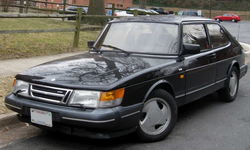
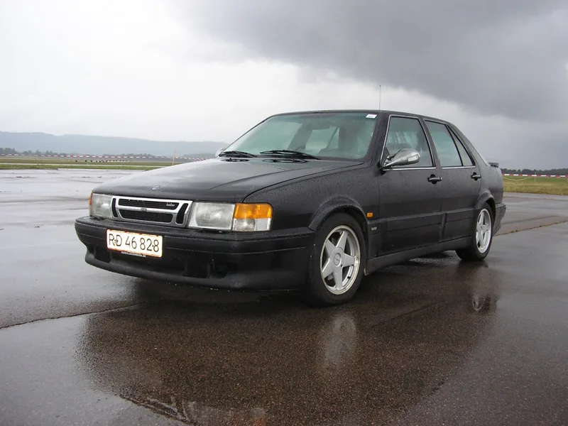
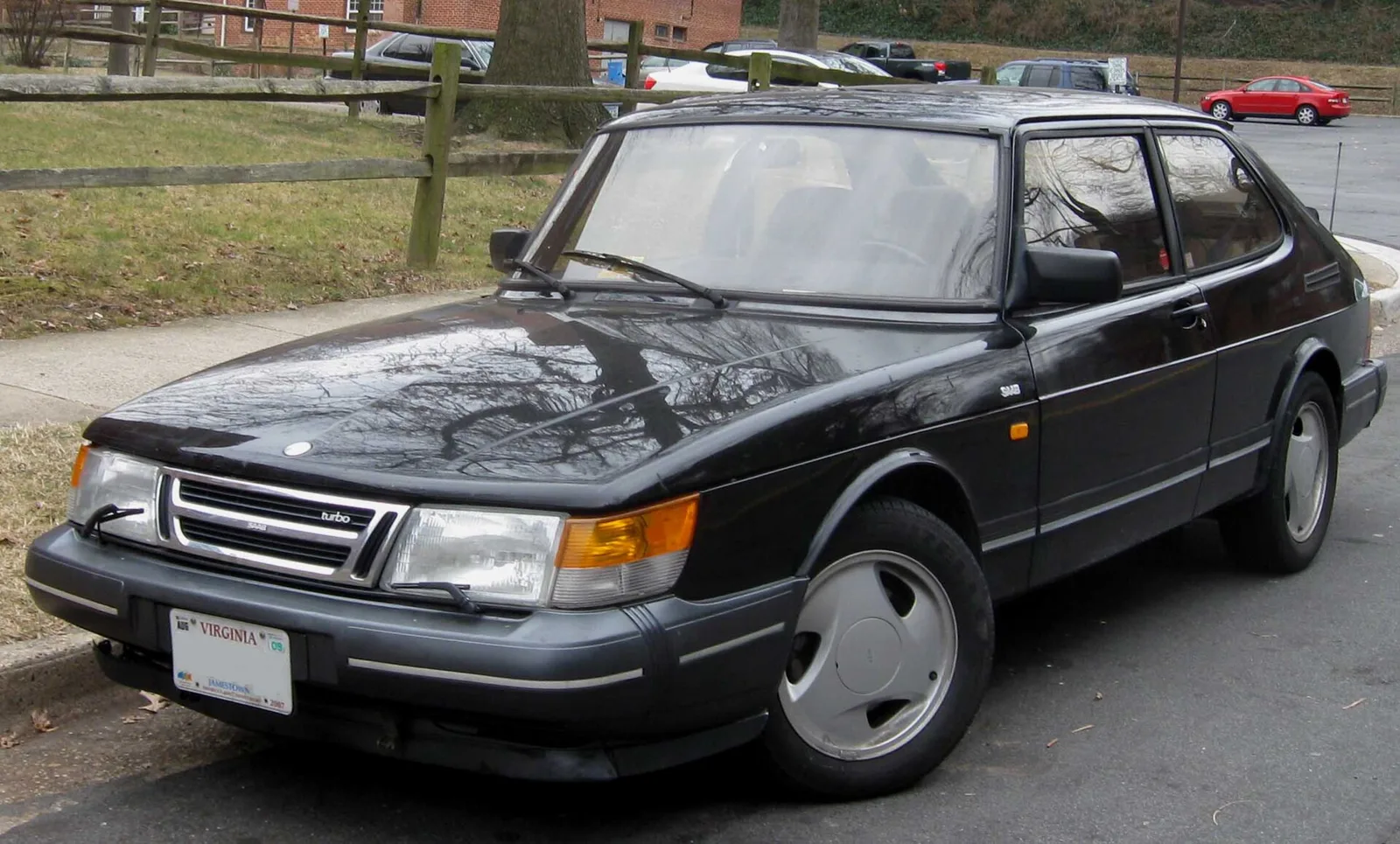
Trionic T5.5 is the engine management system in Saab's Trionic range, which first appeared in a turbocharged 9000 with the B234L and B234R engines. It was fitted to the Saab 900, 9000 and 9-3, although the most detailed documentation covers the 900.
The B234L and B234R were the launch engines, and both were turbocharged. The system's job was to manage ignition timing, fuel injection and boost pressure together, so that each function could respond to the others as conditions changed.
Fitment matters, because details can vary between models. The description is most accurate for the Saab 900, so a reader comparing the 9000 or 9-3 should expect some differences in calibration and in the feature list.
One spark plug did three jobs in Saab's Trionic system: it fired the mixture, sensed the burn and helped detect knock.
How did Trionic T5.5 change from year to year?
The system changed steadily between 1995 and 1998. A four-wire oxygen sensor arrived in 1995, OBD II diagnostics followed on US and Canadian cars in 1996, the heat plates were removed in 1997, and the 1998 Saab 9-3 added new immobilisation and two new engine variants.
The 1995 model year brought the four-wire oxygen sensor and electronic heat plates in the intake manifold, although the plates were not fitted to US and Canadian cars. Some markets also gained K-line immobilising through the Vehicle Security System. Automatic cars received a vacuum pump for the servo-assisted brakes, with some control from the engine unit.
1996 was the year of OBD II. US and Canadian cars carried two lambda probes and OBD II diagnostics, and the evaporative emissions system gained leakage diagnostics on the OBD II variant, so that a leak could be reported to the driver.
The heat plates came out in 1997, which removed one source of intake restriction and the boost compensation that went with it. Engines with the plates had run slightly higher boost to offset that restriction, so the change also affected the boost calibration.
The 1998 Saab 9-3 changes moved immobilising to the Main Instrument Unit, which tied the security function to the car's central electronics. Two new engines appeared that year, the B204R and the B204E, and they gave the range a broader spread of output.
The B204E was the odd one out. It was available with a manual gearbox only, needed high octane petrol to deliver its stated torque and lacked boost pressure control. It was not offered in US or Canadian markets, but Swedish cars carried it with OBD II diagnostics and ORVR vapour recovery.
How does the ignition system work?
The ignition system is capacitive. A cassette sitting on the valve cover holds four coils, one per spark plug, and it boosts battery voltage to 400 V DC stored in a capacitor. The secondary side can reach 40 kV, and the spark plugs also act as combustion sensors.
The cassette takes its supply from the main relay and is grounded at an earth point. The ECU triggers each coil's primary through its own line, and when the primary is grounded the stored energy transforms up to 40 kV in the secondary of that cylinder's coil.
Because the spark plugs double as sensors, the system does not need a camshaft position sensor or a separate knock sensor. Combustion and pre-ignition are detected from the ionisation current, which also makes misfire detection possible, something OBD II requires.
Timing at start-up and idle follows its own maps. Start ignition sits at 10 degrees BTDC. Below 0 C coolant the ECU fires a multi-spark 210 times per second up to 900 rpm, which helps the engine catch. Normal idle ignition is 6 to 8 degrees BTDC.
If the engine stalls, for example when a cooling fan switches on, the ignition can advance to 20 degrees BTDC to restore idle. Once the throttle opens, the ECU leaves the idle map and sets timing by load and speed instead.
How does the ECU detect knock and identify the firing cylinder?
Knock is detected inside the cassette, which monitors ion currents and reports a knock signal on a single ECU pin. Each knock event retards that cylinder's timing by one and a half degrees, up to a total retard of 12 degrees. Without a camshaft sensor, the ECU works out which cylinder has fired by pairing the ionisation signals.
The ionisation current is measured in pairs. Cylinders one and two form one pair, and cylinders three and four form the other, so the ECU can tell which pair has fired and then identify the cylinder from the crankshaft position.
At start-up the ECU does not know which cylinder is on compression, so it initiates ignition in both cylinders one and four. Sparks in cylinders two and three follow half a crankshaft revolution later. Once the combustion pulses arrive on the expected pins, ignition and injection synchronise to the firing order.
Knock logic is adaptive, and the cassette's own logic copes with fuel additives that would otherwise disturb the signal. The ECU reacts in steps. It retards the timing first, and if the same retard appears everywhere it enriches all cylinders slightly. Above 140 kPa of manifold pressure it switches the fuel and ignition matrices before lowering boost.
If the signal between cassette and ECU is lost, boost falls back to basic pressure and timing is retarded where there is a risk of knock under load. That fallback keeps the engine safe even when the sensing path has failed, at the cost of some performance.
How is fuel injection controlled?
Trionic uses fully sequential solenoid injectors with four holes, fixed in pairs. The ECU calculates the air mass in each cylinder, divides it by 14.7 for the stoichiometric fuel mass, and corrects the result with the oxygen sensor so that lambda stays at one.
The injectors draw their supply through the main relay, while the ECU completes the circuit to earth. Each one is a solenoid with a needle and seat, and a strong spring closes it when current stops. The four holes give a good spray distribution, with two jets aimed at the back of each inlet valve.
Pre-injection prepares the engine for a cold start. When the ignition is switched on, the relays run for a few seconds, and a coolant-temperature dependent injection fires all four injectors together. If the engine has run and is then switched off, a new pre-injection occurs after 45 seconds.
Injection time depends on load. It runs from two and a half ms at idle to 18 to 20 ms at full torque, measured on a warm engine with a healthy battery. Lambda correction can adjust the duration by plus or minus 25%, and the oxygen sensor is pre-heated so that it works quickly after start.
The oxygen sensor sits forward in the exhaust and reads the mixture from the voltage it produces. Rich mixtures give a voltage above 0.45 V and lean mixtures one below it. Its heater runs from the main relay and is switched off once exhaust temperature is high, which the ECU estimates from load and rpm.
Enrichment covers the rest of the map. Cold start enrichment applies before lambda control begins, wide-open-throttle enrichment masks lambda correction altogether, acceleration adds fuel as the throttle opens, and deceleration leans the mixture as it closes.
Fuel cut is part of the same strategy. With the throttle closed and engine speed above 1,900 rpm in third to fifth gear, the injectors shut off after a short delay and reactivate at 1,400 rpm. On automatic cars the fuel cut is active in all gears.
What is adaptation and why does it matter?
Adaptation lets the ECU learn from the lambda correction and update its fuel matrix, so driveability, consumption and emissions stay right when lambda control is not active. Pointed adaptation changes single cells, while global adaptation shifts whole areas of the matrix by a single factor.
The basic injection calculation uses manifold pressure and intake temperature, and it is then corrected by a factor from the main fuel matrix, which depends on pressure and rpm. Volumetric efficiency changes with engine speed, which is why the matrix is needed in the first place.
Pointed adaptation works on one cell at a time. If the calculated pulse is 8 ms but the lambda correction needs 9 ms because fuel pressure is low, the cell is changed to 9 ms. That raises the correction factor by 12%, and the cell can change by up to plus or minus 25%.
Global adaptation covers a wider area. When the engine sits in the 60 to 120 kPa and 2,000 to 3,000 rpm range, every point in the matrix is changed by a multiplication factor rather than individually. On OBD II variants it occurs during driving, while on other variants it runs 15 minutes after shutdown.
Both types run on a schedule. Adaptation runs every fifth minute and needs 30 seconds, provided lambda correction is active and coolant is above 64 C. The carbon canister's ventilation valve is held closed during the process, so that fuel vapour does not disturb the reading.
A diagnostic tool could show how far the system had moved. Tech2 displayed global adaptation of up to plus or minus 100%, which made the shift visible to a technician even though the adaptation itself was limited to plus or minus 25%.
How was turbo boost controlled?
Boost was set by a solenoid valve connected to the wastegate. The ECU requested a boost pressure from a matrix of rpm and throttle opening, then corrected the solenoid's pulse width against the pressure sensor, storing the correction in its memory so that it was used from then on.
Basic charging pressure is the mechanical starting point. It is set on the actuator pushrod to forty hundredths of a bar, with a tolerance of three hundredths either way. Too little pressure and the engine fails to rev when the throttle is opened quickly; too much and a negative adaptation stops maximum boost from being reached.
The pushrod must keep at least two turns of pre-tension, which is 2 mm, so that the wastegate is held closed when it is not affected. The pressure tends to fall at high rpm and to rise in cold outside air, so checks must allow for both effects.
The solenoid is a two-coil three-way valve connected to the wastegate, the turbo outlet and the compressor inlet. It is pulse width modulated at 90 Hz below 2,500 rpm and at 70 Hz above, a change made to avoid resonance in the pneumatic hoses.
Boost is limited in several cases. In first, second and reverse gear an rpm-dependent maximum applies, and the ECU identifies the gear by comparing road speed with engine speed. When pre-ignition or pinging occurs, a ceiling is set from the average ignition retard across the cylinders.
Boost drops to basic pressure when the brake pedal is pressed, which the ECU detects through a dedicated input, or when certain fault codes are set or battery voltage is low. In each case the aim is to remove the stress on the engine while the fault is dealt with.
What were the heat plates for?
Heat plates in the intake manifold vaporised injected fuel during warm-up, which cut emissions by reducing the extra fuel needed for a cold mixture. They switched on below 85 C coolant and off above that temperature or after four minutes, and they were removed from 1997 onwards.
The circuit was protected by a 40 A MAXI fuse, and the ECU grounded a relay to switch the plates on. The system was activated entirely by software, which let different algorithms use the plates and compensate for the intake restriction they caused.
Engines with heat plates ran around 0.2 bar more boost to offset the extra restriction, so those cars needed a solenoid valve that could raise boost above basic pressure. Without that adjustment, the restriction would have reduced power at the top end.
A heat plate failure caused drivability problems, because fuel could condense in the cold intake. Engines without heat plates handled the same condensation by enriching the mixture, so the plates were a trade between warm-up emissions and cold running.
Specifications at a glance
| Subsystem | Key figure | Detail |
|---|---|---|
| Introduction | 1993 Saab 9000 2.3 Turbo | B234L and B234R engines |
| Ignition | Four coils, capacitive cassette | 400 V DC stored, up to 40 kV secondary |
| Start and idle ignition | 10 degrees BTDC at start, 6 to 8 degrees at idle | Multi-spark 210 times per second below 0 C coolant |
| Injection | Fully sequential, four-hole solenoid injectors | Two and a half ms at idle, 18 to 20 ms at full torque |
| Lambda correction | Plus or minus 25% | Oxygen sensor switches around 0.45 V |
| Adaptation | Every fifth minute, 30 seconds | Global adaptation 15 minutes after shutdown on non-OBD II cars |
| Basic boost | Forty hundredths of a bar, plus or minus three hundredths | Pushrod pre-tension of at least two turns (2 mm) |
| Boost solenoid | 90 Hz below 2,500 rpm, 70 Hz above | Two-coil three-way valve |
| Heat plates | On below 85 C coolant | Off after four minutes, 40 A MAXI fuse |
| Shift Up lamp | Near 6,000 rpm at wide-open throttle | Not lit in fifth gear |
What other features did the system include?
The Shift Up lamp encouraged economical driving by lighting at a set rpm while the car cruised gently, and it lit at about 6,000 rpm at wide-open throttle. The system also detected misfires from the combustion signals, which OBD II requires, and it added leakage diagnostics for the evaporative system from 1996.
The Shift Up lamp is powered by ignition supply and grounded in the ECU. It lights for three seconds at switch-on to test the circuit, and then glows at a specific rpm while the car is driven gently.
The lamp stays off in fifth gear. When the engine is cold it lights at a higher rpm, which helps the engine warm up more quickly and reduces the time spent in a rich, cold state.
Misfire detection relied on the ionisation signals already used for knock and combustion, so no extra sensor was needed. That reuse of signals was typical of the whole design, in which one spark plug could do three jobs at once.