How a sealed oil-filled coupling transmits power without a friction clutch, from 1905 patents and Daimler luxury cars to locomotives and aircraft engines.
A fluid coupling joins two shafts through a sealed body of oil, so torque moves through fluid instead of friction plates. Its pump and turbine can never match speeds perfectly, so some energy is always lost as heat. It was used in early cars and still runs industrial and rail drives.
A fluid coupling transmits rotating power through a sealed body of oil rather than through friction plates. It was used in car transmissions as an alternative to a mechanical clutch, and it still appears in marine and industrial drives, where variable speed and controlled start-up are essential. The device is a hydrodynamic, or hydrokinetic, unit, so it is different from a hydrostatic drive that relies on a pump and motor.
What is a fluid coupling?
A fluid coupling, also called a hydraulic coupling, is a hydrodynamic device that moves rotating mechanical power from one shaft to another. Its defining feature is that the two shafts never touch in the way a clutch's plates do. Instead, a fluid carries the torque, which means the coupling can start a load gently without the shock a rigid connection would impose.
Engineers distinguish this from hydrostatic drives, which combine a hydraulic pump with a motor. A coupling is a kinetic device, so its performance depends on how fast the fluid is spun rather than on pressure alone. That is why it suits applications with high-inertia starts and loads that cycle repeatedly.
A coupling that never quite locks, and that is why it could start a bus without a jolt.
How did fluid couplings reach the car?
The fluid coupling traces back to Hermann Foettinger, chief designer at the AG Vulcan Works in Stettin. Patents filed in 1905 by Foettinger spanned couplings and torque converters alike, so the two ideas were born together. The concept lay dormant for vehicle use until engineers began looking for a smoother way to start heavy machines.
The move into road transport came through an unusual problem. Harold Sinclair, an English engineer, had experienced the lurching of London buses in the 1920s. Dr Gustav Bauer of the Vulcan-Werke worked with him to adapt Foettinger's coupling to vehicle transmissions. Discussions with the London General Omnibus Company began in October 1926, and trials followed on an Associated Daimler bus chassis.
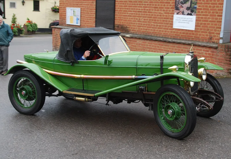
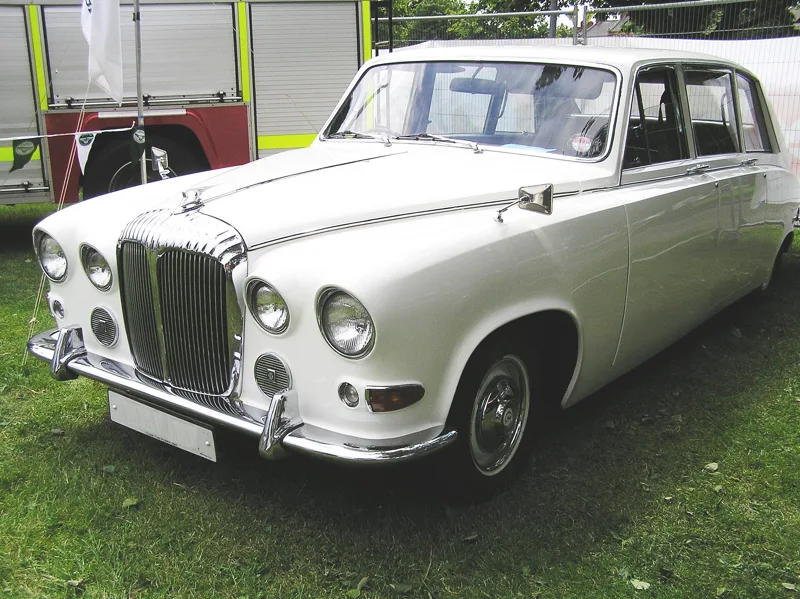
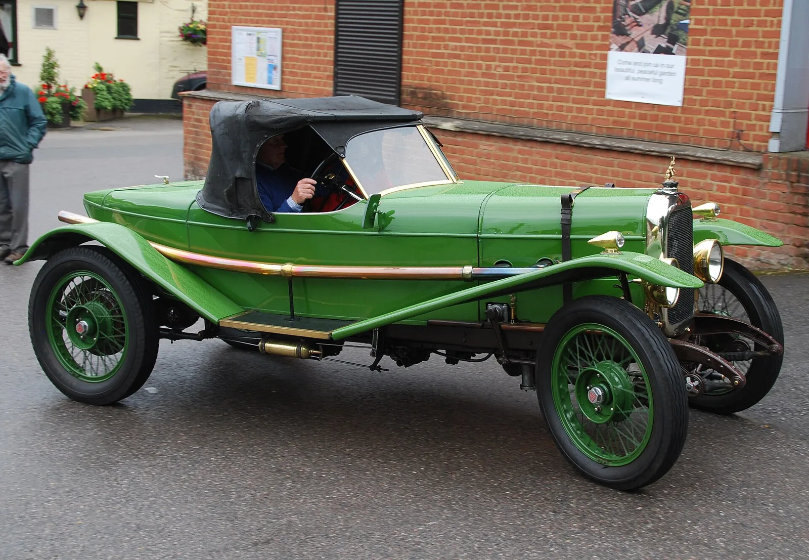
Percy Martin of Daimler then applied the principle to the group's private cars. The Daimler Company of Coventry began introducing a transmission using a fluid coupling and a Wilson self-changing gearbox in 1930. By 1933 the system was fitted to all new Daimler, Lanchester and BSA vehicles, from heavy commercial vehicles to small cars, and in 1934 the Singer Eleven carried it under the Fluidrive name.
What were the key milestones in fluid coupling history?
| Year | Development |
|---|---|
| 1905 | Foettinger patents cover fluid couplings and torque converters |
| 1926 | Talks with the London General Omnibus Company begin in October |
| 1930 | Daimler introduces a fluid coupling with a Wilson self-changing gearbox |
| 1933 | The system is used in all new Daimler, Lanchester and BSA vehicles |
| 1934 | The Singer Eleven is branded Fluidrive |
| 1939 | General Motors introduces Hydramatic drive |
| 1958 | Daimler switches to automatic gearboxes with the Majestic |
In 1939 General Motors brought out Hydramatic drive, which was the first fully automatic transmission installed in a mass-produced car. It used a fluid coupling at its heart. The first diesel locomotives to use fluid couplings also appeared during the 1930s, showing that the principle worked well in rail traction as well as on the road.
How does a fluid coupling transmit power?
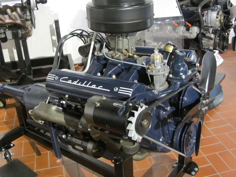
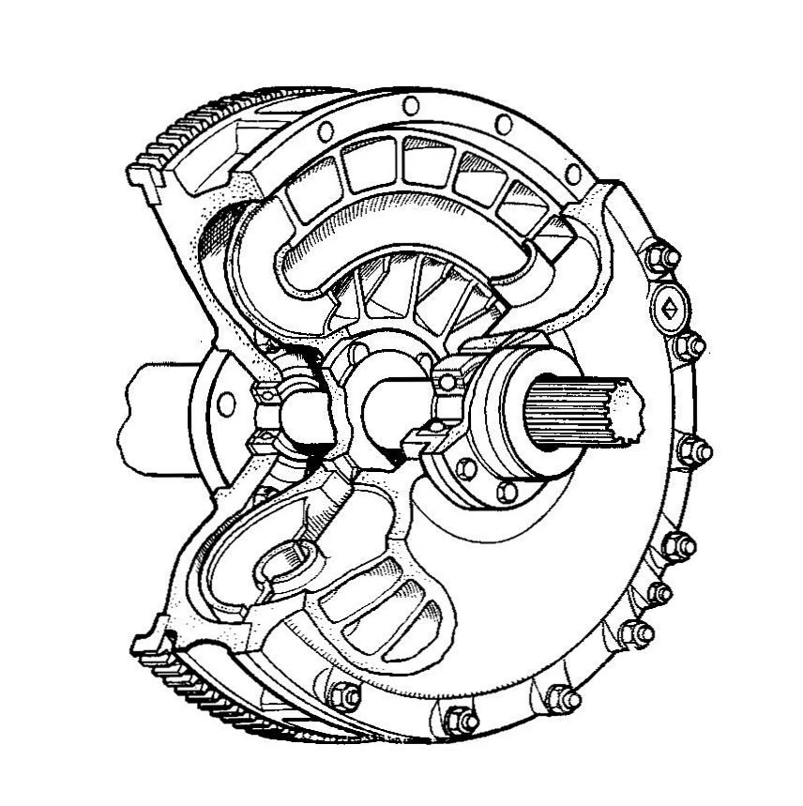
A fluid coupling consists of three components plus the fluid itself. The housing, also called the shell, holds the oil and must be sealed against leaks where the shafts pass through. Inside sit two turbines: the pump, or impeller, which connects to the input shaft, and the turbine, or runner, which connects to the output shaft.
The engine or electric motor turns the pump, and the pump's shape throws the fluid outward and along toward the output turbine. Any difference in angular velocity between the two stages produces a net force on the output turbine, which then turns in step with the pump. Inside the housing the fluid circulates in a toroidal loop, rather like a path running round the surface of an imaginary doughnut.
When the two stages turn at identical speeds, there is no net flow between them, and nothing is transmitted. The coupling only works while the input and output run at different speeds, which is also why it can never be perfectly efficient.
Why do stall speed and slip matter?
Stall speed is the most important characteristic of a fluid coupling. It is defined as the highest speed at which the pump can turn while the output turbine is locked and full input torque is applied. At stall, all the engine's power at that speed is turned into heat inside the fluid, which can damage the coupling if it runs that way for long.
Slip is the price of transmitting power at all. A coupling cannot develop output torque when input and output speeds match, so some power is always lost to fluid friction and turbulence. The efficiency of a fluid device tends to rise with scale, as measured by the Reynolds number, which is why large industrial units do better than small ones.
Which hydraulic fluids are used?
Because a fluid coupling works kinetically, low-viscosity fluids are preferred. Multi-grade motor oils and automatic transmission fluids are the usual choices. Denser fluid carries more torque at a given input speed, but viscosity changes with temperature, which alters transmission performance.
Where performance changes must be kept small, engineers pick a fluid with a high viscosity index, so that its thickness varies less across the operating range. The choice of fluid therefore balances torque capacity against consistency in temperature, and it shapes how the coupling behaves on cold starts as well as on hot days.
How do step-circuit couplings and scoop control work?
A modification called the step-circuit coupling was once made as the STC coupling by the Fluidrive Engineering Company. It contained a reservoir that catches part of the oil when the output shaft stalls. Because less oil circulates, drag on the input shaft falls, which reduces fuel use at idle and cuts the car's tendency to creep. When the output begins to turn, centrifugal force throws the oil back into the main body of the coupling.
Scoop control offers another approach. A non-rotating pipe enters the spinning coupling through a fixed hub, scoops fluid out and returns it to a holding tank. Moving the scoop changes the fill level and so the torque the coupling can transmit. This allows stepless control of very large torques, and it is widely used in variable speed drives. The Fell locomotive was a British experimental diesel of the 1950s. It had four engines and four couplings, and each coupling had its own scoop, so engines could be brought in one at a time.
Correct filling matters for every coupling. An under-filled unit cannot carry full torque, and its limited fluid is likely to overheat, often damaging the seals. Coupling designs that tolerate under-filling usually include an ample reservoir that is kept separate from the impeller.
Where are fluid couplings used today?
Industrial machinery is the main home of the fluid coupling today. Machine drives with high-inertia starts or constant cyclic loading benefit most from its gentle start-up. On railways, Self-Changing Gears made semi-automatic transmissions for British Rail, and Voith manufactured turbo-transmissions for diesel multiple units that combine fluid couplings with torque converters.
Fluid couplings also serve as hydrodynamic brakes. Dissipating rotational energy as heat through fluid friction, they act as a retarder when used that way. Several industrial applications rely on this braking role alongside the normal drive function.
Why did torque converters replace couplings in cars?
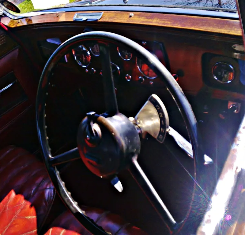
Fluid couplings appeared in a range of early semi-automatic and automatic transmissions. Daimler paired its fluid flywheels with a Wilson pre-selector gearbox across its luxury range, and the combination lasted until the 1958 Majestic brought in automatic gearboxes. Daimler and Alvis also fitted the same pairing to military vehicles and armoured cars.
From the late 1940s onward, car makers turned to the hydrodynamic torque converter instead of the coupling. A converter can multiply torque as well as transmit it, which makes it better suited to the demands of road driving. Even so, the coupling's basic behaviour strongly resembles that of a mechanical clutch driving a manual transmission, which is why it was such a natural step for drivers.
How were fluid couplings used in aircraft?
The most prominent aeronautical use was in the DB 601, DB 603 and DB 605 engines. There a barometrically controlled hydraulic clutch drove the centrifugal compressor. The Wright turbo-compound piston engine offered another example. Three power recovery turbines extracted about 20 percent of the energy from its exhaust, or about 500 horsepower (370 kW). Three fluid couplings and gearing then converted the fast, low-torque turbine rotation into slow, high-torque output for the propeller.