How a dyno turns torque and speed into power, the absorber types behind the numbers, and why engine and chassis figures differ.
Dynamometers measure power by taking torque and rotational speed together, a method used throughout engine development and tuning. Engine and chassis versions exist, and each uses an absorber suited to its task, from eddy current discs to water brakes, and the readings guide tuning decisions.
A dynamometer, or dyno, is a device that measures the torque and rotational speed of an engine, motor or other rotating prime mover at the same time. From those two readings its power can be calculated and shown in kilowatts or brake horsepower.
What does a dynamometer measure?
A dynamometer measures torque and rotational speed simultaneously, so that the machine's instantaneous power can be calculated. The reading is usually displayed by the dynamometer itself as kW or bhp, and it can be used to determine the torque or power characteristics of any machine under test.
Power is calculated as torque multiplied by angular velocity, with a conversion constant where the units require one. In imperial units, horsepower equals torque in pound-feet multiplied by RPM and divided by 5252. In metric units, power in watts equals torque in newton-metres multiplied by angular velocity.
Beyond simple power and torque figures, dynamometers form a testbed for many development tasks. They are used to calibrate engine management controllers, to investigate combustion behaviour and to study tribology.
A dyno turns torque and speed into a power figure, and the choice of absorber decides how that figure is reached.
What are the basic types of dynamometer?
An absorbing dynamometer acts as a load that the prime mover drives, and it must be able to operate at any speed and load the test needs. Its power absorption unit converts the absorbed power into heat, which dissipates into the air or into cooling water.
A motoring dynamometer can also drive the equipment under test, which allows very small outputs to be tested, such as the speeds and loads of travelling downhill. A universal dynamometer combines absorbing and motoring functions, and regenerative units can feed power back into the grid where permitted.
Inertia dynamometers are different. They calculate power solely by measuring the power needed to accelerate a known mass roller, and they provide no variable load to the engine. Their results depend heavily on the mass assumed.
How is torque measured on a dynamometer?
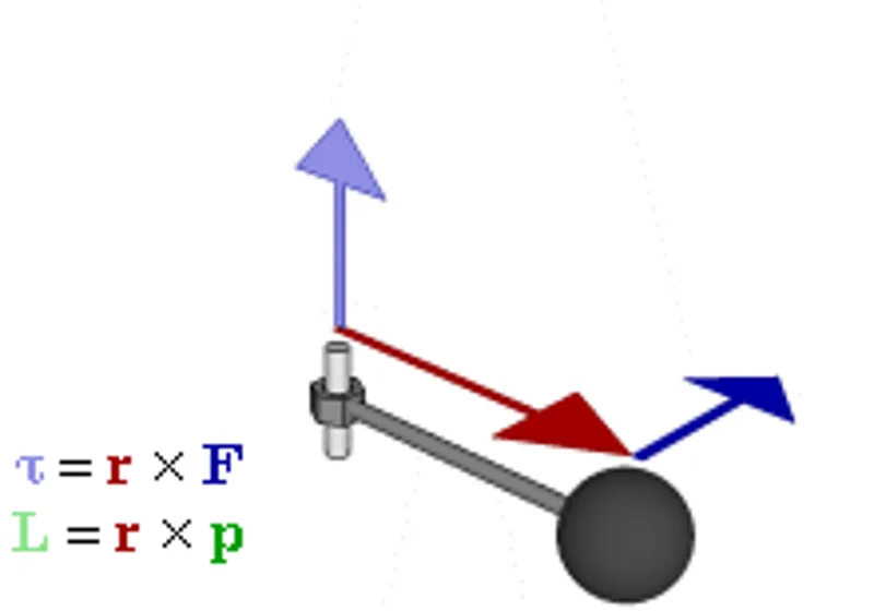
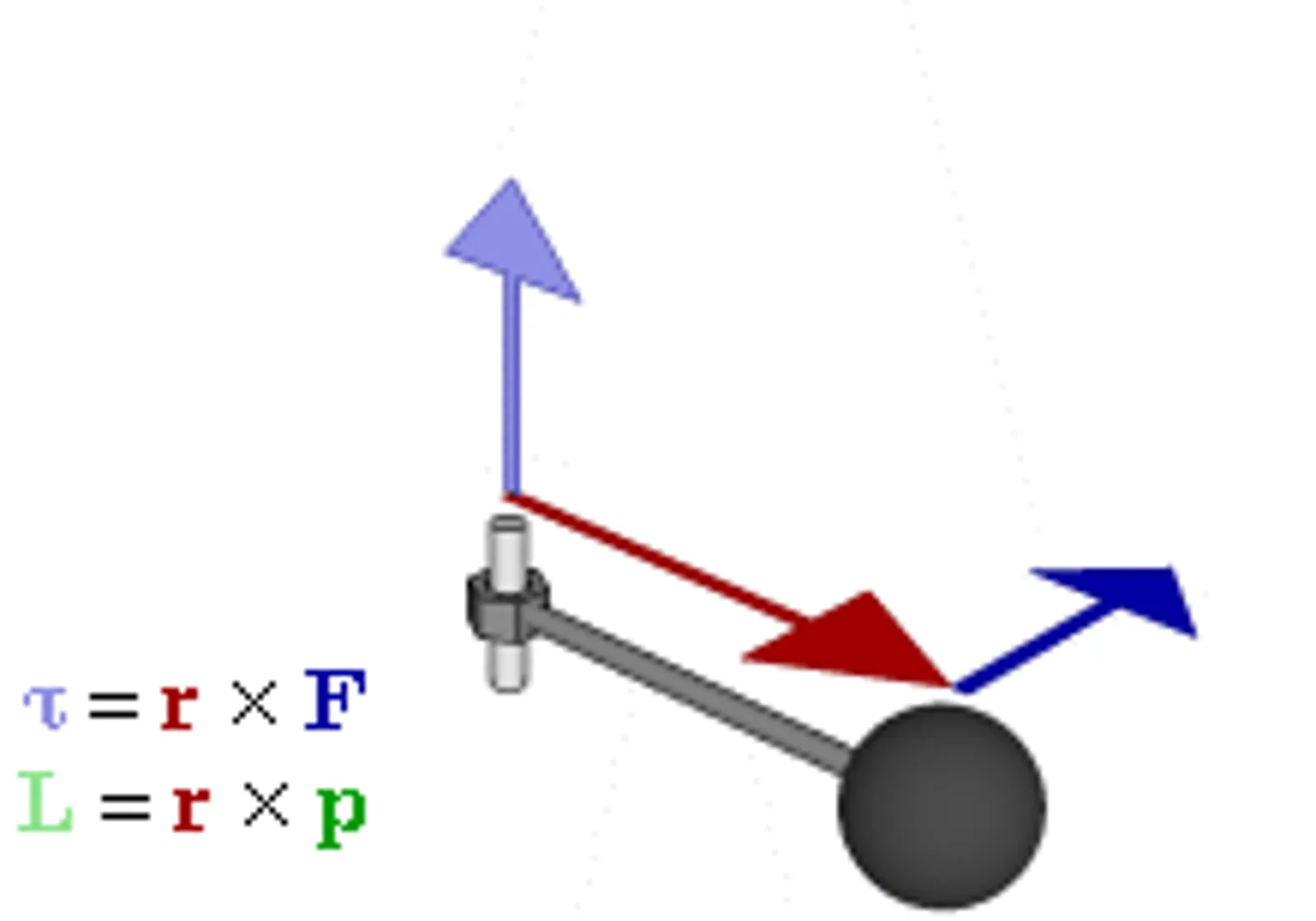
One method mounts the dynamometer housing so that it is free to turn except where restrained by a torque arm. The housing is supported on trunnions, and a weighing scale measures the force it exerts. Torque is that force multiplied by the length of the torque arm, measured from the centre of the dynamometer.
A load cell can replace the scale and give an electrical signal proportional to torque. Another method connects the engine to the dynamometer through a torque transducer in the coupling, which likewise gives a signal proportional to torque.
Torque can also be inferred from the current drawn or generated by an electrical absorber. That approach is less accurate and rarely used today, although it may be adequate for some purposes. Where torque and speed signals exist, data can go to an acquisition system or to a chart recorder.
What absorber types do dynamometers use?
Eddy current dynamometers are the most common absorbers in modern chassis dynos, because they change load quickly and allow rapid settling. Most are air cooled, although some need external water cooling. In current designs, most eddy current brakes use cast iron discs much like vehicle brake rotors, with a computer controlling the electromagnets that set the braking strength.
Hysteresis dynamometers use a magnetic rotor that is cycled through flux lines, and they develop largely constant torque across their speed range. Hysteresis and eddy current technologies are among the most useful for small dynamometers of 200 hp (150 kW) and less.
The hydraulic dynamometer, also called the water brake absorber, was invented by the British engineer William Froude in 1877. He developed it in response to a request by the Admiralty for a machine able to absorb and measure the power of large naval engines.
Water brakes are still relatively common. They are noted for high power capability, small size, light weight and low manufacturing cost, although they can take a long time to stabilise their load and need a steady supply of water for cooling.
A compound dynamometer pairs a larger absorber with a smaller motoring unit. That is cheaper than one machine large enough to do both jobs, and a typical size ratio of about 3:1 suits emissions cycles and most development work, although the transition between motoring and braking needs careful control.
Other absorbers include powder dynamometers, which place a fine magnetic powder in the air gap and are limited to lower RPM by heat, and fan brakes, whose torque is limited by the low viscosity of air. An oil shear brake works like an automatic transmission clutch and is smooth down to zero RPM.
What are engine and chassis dynamometers?
An engine dynamometer measures power and torque directly from the crankshaft or flywheel, with the engine removed from the vehicle. Because it does not include the drivetrain, it does not account for losses in the gearbox, transmission and differential. That makes it the natural place to isolate the engine's own output.
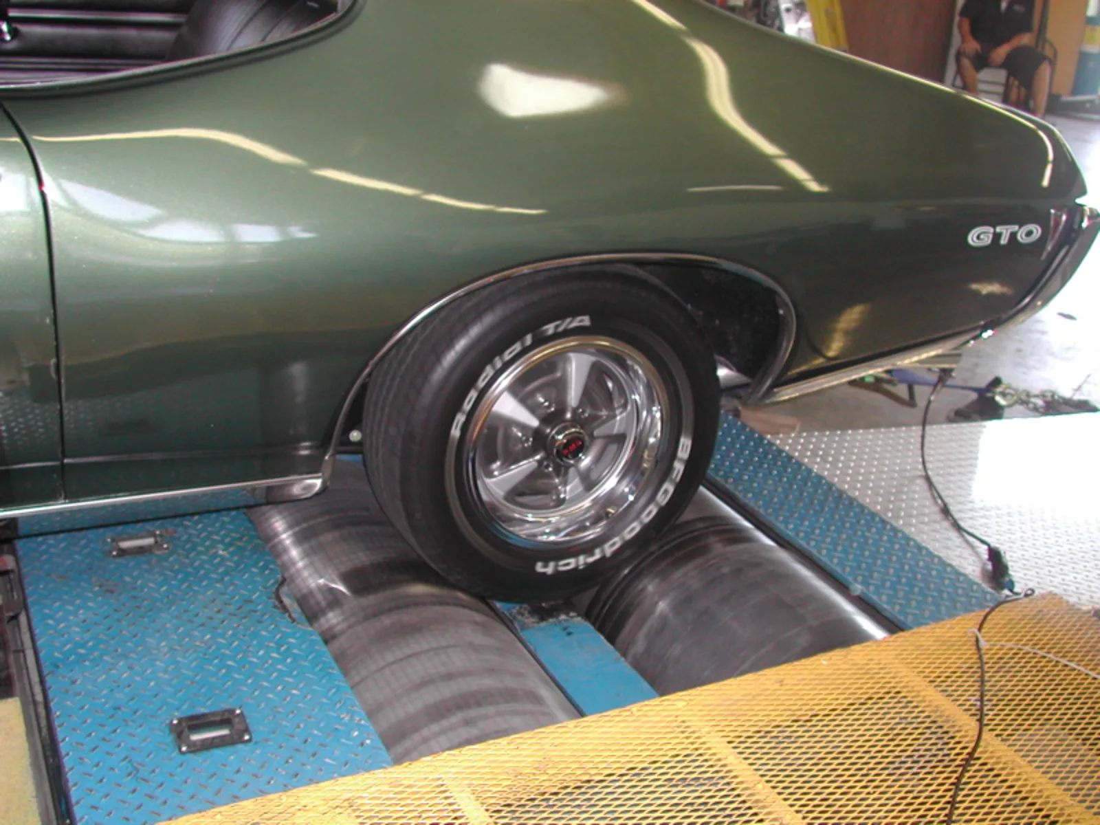
A chassis dynamometer, sometimes called a rolling road, measures the power delivered at the drive wheels. The vehicle is often strapped down on rollers that its wheels turn, and modern systems use the Salvisberg roller, which improves traction and repeatability.
Chassis dynamometers can be fixed or portable, and with modern electronics and low-inertia systems it is now possible to tune for best power and smoothest runs in real time. Other designs attach directly to the vehicle's hubs, measuring torque at the axle and avoiding the wheel slip that older drive rollers allowed.
The two methods answer different questions, so each has its place in development. Each suits a different question about the car. The table compares the main kinds of dynamometer and what each one measures.
| Type | What it measures | Notes |
|---|---|---|
| Engine dynamometer | Power and torque at the crankshaft or flywheel | Engine removed from the vehicle; drivetrain losses not included |
| Chassis dynamometer | Power delivered at the drive wheels | Vehicle strapped to rollers; includes drivetrain losses |
| Brake dynamometer | Engine speed held against a braking load | Used for steady state tests with a power absorption unit |
| Inertia dynamometer | Power needed to accelerate a fixed flywheel mass | No variable load; results depend on assumed mass |
| Motoring dynamometer | Absorbs power and can also drive the engine | Needed for transient tests and very small outputs |
Measured wheel brake horsepower is generally 15 to 20 percent less than the crankshaft figure from an engine dynamometer, because of frictional and mechanical losses in the drivetrain components.
What are the main dynamometer test procedures?
There are essentially three types of dynamometer test procedure. Steady state tests hold the engine at set RPMs for a chosen time under brake loading, sweep tests let the engine accelerate under a load from a starting speed to an end speed, and transient tests vary power and speed through a test cycle.
Transient tests are usually run on AC or DC dynamometers, and different jurisdictions use different cycles. Each jurisdiction uses its own list. Among the US light-duty chassis cycles are UDDS and HWFET, and engine cycles include ETC and WHTC.
Sweep tests have a weakness. An inertia sweep does not know the real rotating mass of the engine or vehicle, and the variability of even tyre mass skews results. High-power engines can finish a fourth-gear sweep in under 10 seconds, which is not a reliable load condition compared with real driving.
Steady state testing avoids that error entirely, because there is no acceleration during the test. Transient tests need motoring capability, because an eddy current system alone will generate different emissions results for the same cycle.
How do dynamometers help engine development?
Dynamometers help refine modern engine technology by showing how much power is lost between the engine and the wheels. Comparing an engine dyno figure with a chassis dyno figure shows how much the drivetrain takes. Dynamometers are expensive, so they are normally used only in fields that rely on them for a particular purpose.
For example, an engine that reads 400 N m (295 lbf ft) on an engine dyno but 350 N m (258 lbf ft) on a chassis dyno shows how much of its output the drivetrain absorbs before the wheels receive it. When torque and speed signals are available, test data can also go straight to an acquisition system rather than being recorded by hand.
Development test cells combine emissions sampling, measurement, engine speed and load control, data acquisition and safety monitoring. Their analysers respond in well under one second, which transient cycles require. In retail tuning, a wideband oxygen sensor graphed alongside RPM is commonly used to set the air-fuel ratio.
Automatic calibration tools vary load and speed across many engine operating points while recording the results. The data can then generate engine calibration tables for the management software.
How did the dynamometer develop?
Several inventors contributed over two centuries. George Graham devised the Graham-Desaguliers dynamometer, which John Desaguliers described in writing in 1719 and later modified. The Regnier dynamometer was made public in 1798 by Edme Regnier, a French rifle maker and engineer.
Gaspard de Prony invented the de Prony brake in 1821, and John Macneill developed a road indicator in the late 1820s to build on a patented weighing machine. Froude of Worcester, which traces its origins to Heenan and Froude, credits William Froude with the hydraulic dynamometer of 1877, and says the first commercial dynamometers came in 1881.
In 1928 the German firm Carl Schenck built the first vehicle dynamometers for brake tests, a design that resembles modern test stands. Martin and Anthony Winther are credited with the eddy current dynamometer around 1931, and their company Dynamatic made dynamometers in Kenosha, Wisconsin until 2002.
Are dynamometers used outside the engine room?
Yes. In medicine, hand-held dynamometers are used for routine screening of grip and hand strength, and for evaluating patients with hand trauma or dysfunction. They also measure grip strength where the cervical nerve roots or peripheral nerves may be compromised.
In rehabilitation, kinesiology and ergonomics, force dynamometers measure the strength of athletes, patients and workers. The force applied to a lever or cable is measured and multiplied by its perpendicular distance from the axis of the lever to give the moment of force.